
Choosing the right PV Cable Harness is a practical decision that affects safety, energy yield, and long-term maintenance. It connects solar modules, inverters, combiner boxes, and other system components. A suitable harness must handle outdoor exposure, electrical loads, temperature changes, and repeated installation stresses.
Start with the system’s voltage, current, cable length, and connector type. These details are not optional. The conductor size should limit voltage drop without creating unnecessary cost or weight. Insulation should resist ultraviolet radiation, moisture, heat, and mechanical damage. Certified connectors also matter because poor contact can create heat at the connection point. In field installations, a loose crimp may remain unnoticed until performance declines or a technician finds discoloration near the terminal.
Experience shows that visual inspection alone is unreliable. A cable may appear strong while its crimp quality is poor. Check manufacturer specifications, compatibility records, conductor materials, bend radius, and environmental ratings. Consider installation conditions, including rooftop temperatures, wind movement, exposed cable sections, and possible contact with sharp edges. It is easy to focus only on the panel rating and overlook the complete electrical path. That mistake deserves careful review. A qualified installer should verify polarity, continuity, insulation condition, and connector engagement before commissioning. Documentation supports accountability and makes future troubleshooting faster. The right PV Cable Harness is not simply the cheapest or thickest option. It is the one that matches the system design, installation environment, and verified quality requirements. Small details matter.
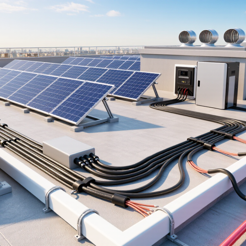
A PV cable harness connects solar modules to combiner boxes, inverters, and other DC equipment. It carries generated current through outdoor conditions. Rooftop heat, rain, ultraviolet exposure, and wind all affect its performance.
Its structure usually includes Solar Cables, crimped terminals, connectors, seals, and branch sections. The cable contains a stranded copper conductor, insulation, and an outer protective jacket. The insulation must resist heat and sunlight. The connector body should maintain secure contact and prevent water entry. Small details matter.
A suitable harness begins with electrical calculations. Check the system voltage, operating current, short-circuit current, and conductor cross-section. Confirm connector compatibility, polarity, temperature range, and bending radius. A cable that looks thick may still have unsuitable insulation or poor crimp quality. Use documented test results and applicable electrical standards as references.
During installation, keep connectors clean and fully locked. Avoid sharp bends near terminals. Leave enough length for thermal movement, but do not create loose loops that collect water. I have found that neat routing can hide weak crimps. A simple pull test and visual inspection often reveal problems early. Still, field conditions are rarely perfect. Dust, rushed work, and uneven cable lengths can reduce reliability. That is why harness selection should consider both the product structure and the actual installation environment.
A PV cable harness should match the system’s maximum voltage, not its average operating voltage. Check the module string voltage during the coldest expected conditions. Low temperatures can increase open-circuit voltage and stress insulation. Leave a suitable safety margin.
Current selection needs equal care. Add the expected operating current, then consider irradiance, cable length, and installation conditions. Long cable runs create voltage drop and energy loss. Undersized conductors may also heat inside crowded conduits. I have seen neat-looking harnesses fail because current calculations ignored grouping.
The environment often decides the cable’s real service life. Outdoor harnesses face ultraviolet exposure, rain, condensation, dust, and sharp temperature changes. Select insulation rated for solar applications and the local temperature range. Check resistance to moisture, ozone, and mechanical abrasion. Connectors must fit securely and maintain proper polarity. Loose contacts can create hot spots.
Inspect the routing path before ordering. A cable crossing a metal edge needs protection. A hanging section needs strain relief. Small details matter. Keep bending within the manufacturer’s stated radius, especially near connectors. Do not assume a higher current rating solves every problem. Heat, sunlight, and poor routing can reduce performance. My own early designs sometimes focused too heavily on electrical ratings. The installation environment deserved more attention. Even a correct calculation can fail in the field.
Choosing a PV cable harness starts with the site, not the catalog. A rooftop array faces heat, water, ultraviolet exposure, and tight routing spaces. For exposed runs, cross-linked photovoltaic insulation usually offers stronger weather resistance than ordinary building wire. Consider copper conductors with suitable tin plating when corrosion is a concern. Confirm conductor size against current, voltage drop, ambient temperature, and installation length. Small details matter.
Connectors need equal attention. They should match the cable diameter, contact design, and environmental rating. A connector that clicks firmly may still be poorly crimped inside. Use the specified crimp profile and inspect the joint for loose strands or uneven compression. Never mix mating parts without verified compatibility, even when their shapes appear identical. Site inspections often reveal rushed assembly, hidden resistance, and later heating. That lesson stays with installers.
Insulation selection should reflect the actual environment, not an ideal test room. Choose materials rated for expected temperature, moisture, sunlight, and mechanical movement. Flexible cable helps around trackers, but excessive bending can still damage insulation over time. Secure harnesses away from sharp edges and avoid tight loops that retain water. Check applicable photovoltaic and electrical standards before installation. I would also record torque, crimp height, and inspection results. Records improve traceability, although they cannot repair a careless connection. A second inspection is worthwhile.
Selecting the correct photovoltaic cable harness requires matching the insulation material, connector specifications, conductor size, voltage rating, and outdoor durability to the installation environment.
The chart compares commonly used insulation systems by maximum continuous conductor operating temperature. PVC is generally rated at 70°C, while cross-linked insulation systems used in photovoltaic cables are commonly rated at 90°C. Choose connectors with compatible cable cross-sections, voltage and current ratings, UV resistance, and an appropriate outdoor protection level. Always verify the final selection against the applicable cable and connector datasheets and installation conditions.
Choosing the right PV cable harness starts with compatibility, not appearance. Match the harness voltage and current ratings with the array and inverter requirements. Check conductor size, insulation type, connector dimensions, and polarity. A harness may fit physically but still fail electrically. Confirm its operating temperature range, UV resistance, water protection, and bend radius before installation.
Safety ratings deserve careful attention. Select cables tested for photovoltaic use, such as those meeting recognized IEC or equivalent national standards. Verify flame performance, insulation durability, and resistance to moisture. Installation must follow local electrical codes and the equipment manufacturer’s instructions. Keep cables away from sharp metal edges and hot surfaces. Use proper crimping tools and inspect every connection. I once found a loose crimp during a field inspection; the cable looked perfect from outside. That mistake was easy to miss.
Tips
Measure the cable route before ordering. Leave enough length for movement, service loops, and thermal expansion. Avoid tight bends and unsupported hanging sections. Secure the harness with UV-resistant clips, not ordinary indoor ties. Check connector locking by hand after assembly. Then test continuity, polarity, insulation resistance, and protective grounding with suitable instruments. Record the test results. Do not assume a factory-made harness needs no inspection. Even a well-made assembly can be damaged during transport or installation. Rechecking takes minutes, while correcting a hidden fault may require dismantling panels.
| Selection Dimension | Recommended Requirement | What to Verify | Installation or Design Consideration | Status |
|---|---|---|---|---|
| Electrical System Compatibility | Use a cable harness with a DC voltage rating equal to or higher than the maximum system voltage. | Confirm the harness rating against the PV system design voltage, including the open-circuit voltage at the lowest expected temperature. | Common PV cable ratings include 1,000 V DC and 1,500 V DC. Do not mix components with lower voltage ratings. | Required |
| Current-Carrying Capacity | Select the conductor cross-section based on maximum operating current, installation method, ambient temperature, and grouping. | Check the cable ampacity after applying applicable derating factors. | Typical PV conductor sizes include 4 mm² and 6 mm², but the correct size must be calculated for the specific installation. | Required |
| Conductor Material | Use stranded, flexible copper conductors designed for photovoltaic applications. | Verify conductor size, strand construction, and resistance values in the technical documentation. | Copper conductors provide reliable crimping and low electrical resistance when correctly terminated. | Recommended |
| Insulation and Sheath | Choose double-insulated, halogen-free insulation and sheath materials intended for outdoor PV service. | Check resistance to UV radiation, ozone, moisture, abrasion, and temperature cycling. | PV cables are commonly constructed with cross-linked insulation materials suitable for long-term outdoor exposure. | Required |
| Temperature Rating | The cable must withstand the expected minimum and maximum operating temperatures. | Verify the marked temperature range and the conductor operating temperature, commonly up to 90°C for PV cables. | Account for higher temperatures inside cable trays, near modules, under roofing, or in poorly ventilated areas. | Required |
| Applicable Cable Standard | Select cables manufactured and tested to a recognized photovoltaic cable standard. | Look for compliance with EN 50618 or IEC 62930, where applicable to the project location. | Project specifications and local electrical regulations may require additional national approvals or test documentation. | Required |
| Connector Compatibility | Use mating connectors that are electrically and mechanically approved for use together. | Confirm connector type, voltage rating, current rating, contact material, sealing system, and locking method. | Do not mate connectors from different product systems unless the manufacturer or applicable certification specifically permits it. | Critical |
| Connector Protection | Connectors should provide suitable protection against dust and water when fully mated and correctly installed. | Verify the required ingress protection rating for the project environment and ensure seals are undamaged. | Keep connectors off the ground, avoid water traps, and do not leave unused connectors exposed to standing water. | Required |
| Crimping Quality | Use the correct contact, conductor size, and calibrated crimping tool. | Inspect crimp height, conductor insertion, pull-out strength, contact retention, and visible damage. | Improper crimping can cause high resistance, localized heating, arcing, and premature failure. | Critical |
| Cable Routing | Route cables to avoid sharp edges, excessive bending, crushing, and contact with hot surfaces. | Check the manufacturer’s minimum bending radius and maintain separation from abrasive or high-temperature structures. | Support cables with UV-resistant clips or ties; do not allow cable weight to hang from connectors. | Required |
| Polarity and String Identification | Clearly identify positive and negative conductors and preserve correct string polarity throughout installation. | Test polarity and continuity before connecting strings to inverters or combiner equipment. | Incorrect polarity can damage equipment and create dangerous troubleshooting conditions. | Critical |
| Grounding and Bonding | Provide protective earthing and bonding in accordance with the applicable electrical code. | Confirm whether the PV module frames, mounting system, cable trays, and other conductive parts require bonding. | PV cable harnesses do not replace protective earth conductors where a separate grounding conductor is required. | Required |
| Environmental Exposure | Match the harness construction to the site conditions, including UV exposure, humidity, salt mist, dust, and chemicals. | Review environmental test results and confirm suitability for rooftop, ground-mounted, coastal, or agricultural installations. | Coastal and industrial locations may require enhanced corrosion protection for connectors and mounting hardware. | Site-Specific |
| Fire Performance | Use cables with the fire performance required by local building and electrical regulations. | Check flame propagation, smoke, and halogen requirements specified for the building or installation type. | Requirements may differ between rooftop systems, building-integrated PV, façades, and utility-scale arrays. | Code-Based |
| Testing Before Energization | Complete installation inspection and electrical testing before the PV system is energized. | Perform polarity, continuity, insulation resistance, open-circuit voltage, and connector inspection tests as required. | Record test results, cable routes, string identification, and any corrective actions for future maintenance. | Required |
| Documentation and Traceability | Keep technical datasheets, certificates, installation instructions, and inspection records. | Verify cable markings, batch information, ratings, standards, and approved connector combinations. | Complete documentation supports commissioning, warranty evaluation, maintenance, and regulatory inspections. | Recommended |
Choosing a PV cable harness requires more than checking conductor size. In field inspections, I look first at crimp consistency, insulation condition, and connector fit. A clean cut matters. Stray strands can create resistance and local heating. Quality harnesses use stable materials, accurate stripping, and controlled crimp pressure. Each termination should withstand a gentle pull test without movement. Documentation also matters. Test records make later troubleshooting less dependent on guesswork.
Durability is tested by time, not appearance. Solar cables face ultraviolet radiation, rain, dust, temperature swings, and repeated expansion. Look for insulation rated for outdoor service and a cable route that respects the specified bend radius. Connectors should lock firmly and remain protected from standing water. Small installation errors become expensive. A cable touching a sharp frame edge may fail after months of vibration. I have seen tidy arrays develop faults because clamps compressed the insulation.
Long-term maintenance should be part of the selection conversation. Choose harnesses that permit visual checks, electrical testing, and practical replacement without disturbing nearby modules. Record cable locations, connector pairs, torque values, and inspection dates. Thermal imaging can reveal abnormal heating, but it should support, not replace, physical inspection. I once trusted a simple continuity check too much; the circuit passed, yet a weak crimp appeared under load. That mistake changed my maintenance routine. Durable design reduces visits, but it never removes the need for disciplined inspection.
By continuing to use the site, you agree to the use of cookies. more information
The cookie settings on this website are set to "allow cookies" to give you the best browsing experience possible. If you continue to use this website without changing your cookie settings or you click "Accept" below then you are consenting to this.