
Buying an Electric Furnace Transformer is a serious decision for any metalworking plant. The right unit must support furnace demand, withstand harsh operating conditions, and protect production continuity. A poor match can cause voltage instability, overheating, unexpected downtime, and costly maintenance.
This guide presents seven practical tips based on transformer selection experience, manufacturer recommendations, and industrial power requirements. It examines capacity, voltage, impedance, cooling methods, insulation, protection systems, supplier reliability, and long-term service support. Each detail matters. A transformer may look suitable on paper, yet perform poorly beside a furnace with frequent load changes. Real operating data is more valuable than a polished brochure.
Check the furnace duty cycle carefully. Measure starting currents, harmonics, ambient temperature, and expected future expansion. Ask qualified engineers to verify calculations against applicable IEC, IEEE, and local utility requirements. Certification alone does not guarantee a perfect fit. It helps, but verification remains essential. Site conditions can expose weaknesses that factory testing never reveals.
Do not focus only on the purchase price. Short-term savings may become higher losses, longer outages, or difficult spare-parts sourcing. Review factory test records, warranty terms, inspection procedures, and the supplier’s field experience. Speak with operators who have used similar equipment. Their practical comments may reveal vibration, noise, or cooling issues overlooked during procurement.
A careful decision protects more than equipment. It supports safety, efficiency, production quality, and predictable operating costs. No selection process is flawless. Recheck assumptions before signing the order. Small oversights can become expensive lessons.
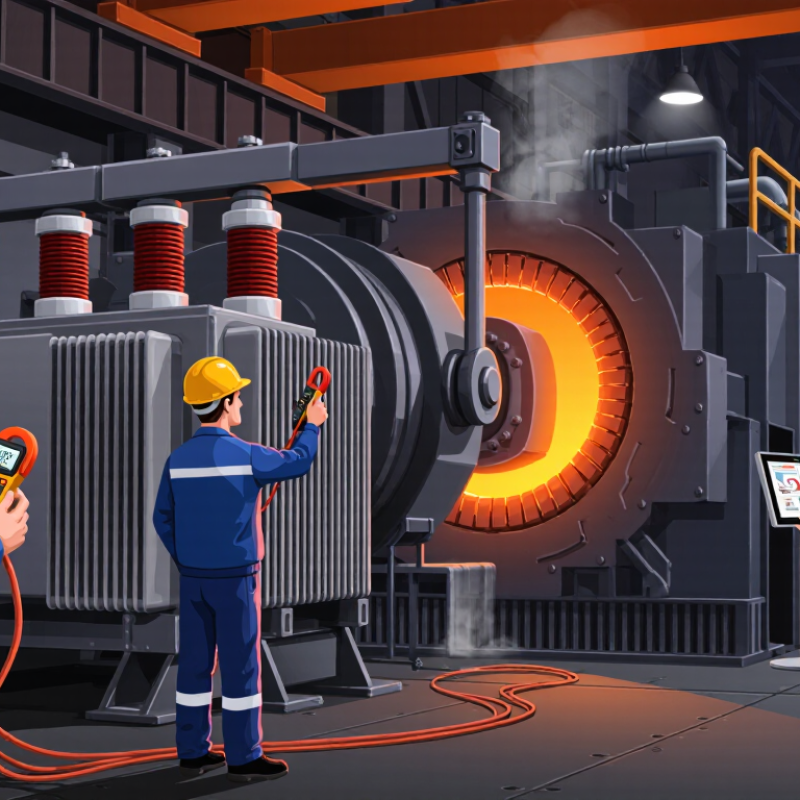
7 Tips for Buying an Electric Furnace Transformer
Define the furnace’s electrical and operating requirements before comparing transformer prices. Start with the furnace’s rated voltage, phase, frequency, and maximum load. Record the required kVA, not only the heating capacity. Measure it twice. A mismatch can cause overheating, nuisance trips, or unstable temperature control.
In field assessments, I check startup current, duty cycle, and expected daily operating hours. Some furnaces draw sharp current pulses during heating cycles. Others run continuously near full load. These patterns affect transformer sizing and cooling requirements. Confirm the primary voltage and allowable tap range with the electrical designer. Also document the secondary voltage at the furnace terminals, because long cable runs can create noticeable voltage drop.
Do not overlook the installation environment. Record ambient temperature, altitude, dust levels, moisture, and available ventilation space. Harmonic-producing controls may require additional capacity or a suitable transformer design. Check the available short-circuit current and protective device settings with a qualified engineer. I have seen projects rely on estimated data, then revise the transformer after commissioning. That delay is avoidable, although field conditions can still differ from drawings. Keep measured readings, operating logs, and furnace control information together. Small errors matter.
Electric Furnace Transformer Sizing Reference
This chart compares common transformer capacity points with their calculated full-load current on a 400 V three-phase supply. Current is calculated using I = kVA × 1000 ÷ (√3 × V). Confirm the furnace’s rated voltage, phase, power factor, duty cycle, heating-element resistance, control loads, and inrush requirements before selecting the transformer.
Tip 1: Calculate capacity from maximum demand, not furnace nameplate power. For a three-phase unit, kVA equals 1.732 × voltage × current. Include power factor, motor loads, and auxiliary equipment.
Tip 2: Model the duty cycle. Furnace current may surge during heating, pause during charging, and fall during holding. A transformer rated for average load can still overheat during repeated peaks. IEC 60076-7 links loading, ambient temperature, and insulation aging.
Tip 3: Confirm primary and secondary voltage carefully. Check tap range, frequency, phase sequence, and allowable voltage variation.
Tip 4: Review short-circuit strength and impedance with the electrical engineer. Low impedance supports voltage stability but can increase fault current. The choice is rarely simple.
Tip 5: Allow for harmonics from power controls. IEEE 519-2022 provides planning guidance for harmonic distortion, while thermal calculations should consider additional winding heating.
Tip 6: Compare efficiency across the real operating profile. The U.S. Department of Energy’s transformer technical documents estimate transformer losses at about 2.5% of national electricity use. Its 2024 final rule projects 3.6 quadrillion Btu in energy savings over thirty years. Small losses become expensive at continuous furnace duty.
Tip 7: Request test data, temperature-rise limits, sound levels, and overload assumptions. A neat 100% capacity match may still be wrong. I would revisit the calculation using measured demand after commissioning, because production schedules often change faster than specifications.
Buying an electric furnace transformer requires more than comparing nameplate capacity. Check full-load efficiency, no-load losses, impedance, and voltage stability. The U.S. Department of Energy’s 2024 distribution transformer rule projects 3.6 quadrillion Btu in energy savings over 30 years. Even small losses matter during continuous furnace operation. Ask for certified test data, not estimates.
Cooling deserves close attention. Oil-immersed, forced-air, and dry-type designs behave differently in dusty, hot rooms. Confirm the temperature-rise rating, fan redundancy, alarm points, and cleaning access. A blocked radiator can quietly reduce transformer life. Insulation should match heat, moisture, switching surges, and furnace harmonics. Request partial-discharge results and impulse-test records aligned with IEC 60076 or applicable IEEE standards. Standards help, but they do not replace site measurements.
Safety features must fit the installation. Review grounding, pressure relief, fire separation, door interlocks, emergency shutdowns, and arc-flash labeling. NFPA 70 and NFPA 70E provide important electrical safety guidance, while IEEE C57.12.01 addresses transformer construction requirements. Verify short-circuit withstand capability with the facility’s fault study. Do not rely on a generic safety statement. A useful checklist should include service clearance, spare sensors, oil containment where applicable, and maintenance intervals. My own caution is simple: efficiency ratings can look excellent on paper, yet poor cooling or unstable loading may erase those gains.
| No. | Evaluation Area | What to Check | Practical Benchmark | Why It Matters | Buyer Action |
|---|---|---|---|---|---|
| 1 | Efficiency and Losses | Review guaranteed no-load loss, load loss, total loss, and efficiency at the expected operating load. | Compare tested or guaranteed values at the required frequency, voltage, temperature, and load. For industrial units, ask for efficiency data at 50%, 75%, and 100% load rather than relying only on a single peak figure. | Lower losses reduce electricity consumption, operating temperature, and lifetime energy cost. | Request a loss schedule and calculate total ownership cost over the expected service life. |
| 2 | Cooling System | Identify the cooling method, rated capacity, ventilation requirements, fan controls, alarms, and redundancy. | Common arrangements include natural-air cooling for lower ratings and forced-air cooling for higher thermal loads. Forced-air fans should have temperature control, overload protection, and accessible filters or guards where applicable. | Correct cooling prevents insulation aging, nuisance trips, and premature failure during continuous furnace operation. | Verify that the transformer room has adequate airflow and that the cooling rating matches the furnace duty cycle. |
| 3 | Insulation System | Check insulation class, temperature-rise rating, dielectric strength, clearances, and suitability for heat, dust, vibration, and humidity. | Dry-type industrial transformers commonly use Class F or Class H insulation systems. The selected design should provide sufficient thermal margin for the ambient temperature and the furnace's harmonic or cyclic load. | Higher thermal capability helps maintain insulation life when the transformer operates near its rated load. | Confirm the insulation system and temperature rise in the technical specification, not only in marketing literature. |
| 4 | Electrical Safety | Evaluate enclosure protection, grounding provisions, overcurrent protection, short-circuit withstand, emergency isolation, and touch-safe barriers. | The enclosure should be selected for the installation environment, such as indoor industrial service or a dusty area. Grounding terminals, clearly identified disconnects, and properly coordinated protective devices are essential. | These features reduce the risk of electric shock, arc faults, fire, and damage caused by abnormal current. | Have the protection scheme reviewed by a qualified electrical engineer before purchase and installation. |
| 5 | Voltage, Capacity, and Load Profile | Match primary voltage, secondary voltage, frequency, phase configuration, kVA rating, tap range, and furnace inrush or cyclic demand. | Allow for the actual maximum demand and foreseeable expansion. A common engineering practice is to avoid continuous operation at the absolute nameplate limit and to assess voltage drop during furnace starting or rapid load changes. | An incorrect rating can cause overheating, poor furnace performance, nuisance trips, or unstable secondary voltage. | Provide the supplier with measured demand, duty cycle, power factor, harmonic information, and starting-current data. |
| 6 | Controls, Monitoring, and Maintenance | Look for winding-temperature sensors, over-temperature alarms, fan-status feedback, power monitoring, inspection access, and spare-parts availability. | Useful monitoring includes separate warning and trip levels, remote alarm contacts, temperature indication, and accessible terminals. Maintenance intervals should be defined for cleaning, tightening, thermal inspection, and fan testing. | Early warnings help operators correct overheating or ventilation problems before an unplanned shutdown occurs. | Specify the required alarm outputs and maintenance access before the enclosure and control panel are finalized. |
| 7 | Standards, Testing, and Documentation | Confirm applicable transformer standards, routine test reports, installation drawings, wiring diagrams, nameplate data, and operating instructions. | Depending on the installation location, documentation may reference recognized requirements such as IEC 60076 or applicable national and local electrical codes. Routine tests commonly include winding resistance, turns ratio, polarity or phase relation, insulation resistance, and applied-voltage tests. | Traceable testing and complete documentation support safe commissioning, maintenance, inspections, and warranty decisions. | Make compliance documents, certified drawings, test results, and acceptance criteria part of the purchase contract. |
Buying an electric furnace transformer requires more than comparing the purchase price. In plant projects, I have seen low bids become expensive after repeated thermal alarms, delayed parts, and poor voltage regulation. Ask suppliers for proven experience with your furnace type, load profile, kVA demand, harmonics, and duty cycle. Request test records, efficiency data, and references from facilities with similar operating conditions. A polished brochure is not enough.
Lifecycle cost deserves a simple worksheet. Include energy losses, cooling power, maintenance labor, oil testing, spare parts, installation, and planned downtime. A transformer with a higher initial price may reduce operating losses for years. Check the expected service life under your actual ambient temperature and furnace cycling. Do not trust generic assumptions. Your numbers may be different. I once underestimated short, repeated heat cycles; the maintenance forecast became too optimistic.
Warranty language needs careful reading. Confirm coverage periods, exclusions, inspection duties, and who pays transportation or field labor. Ask how quickly the supplier can investigate a failure. Technical support should include commissioning guidance, protection settings, troubleshooting, and access to trained engineers. Clarify response times in writing, including nights and weekends. Spare bushing, fan, gasket, and monitoring components may prevent a long shutdown. That detail matters. Also ask whether software, drawings, and test documents remain available after installation. A supplier that answers difficult questions clearly is often safer than one offering the shortest delivery date.
By continuing to use the site, you agree to the use of cookies. more information
The cookie settings on this website are set to "allow cookies" to give you the best browsing experience possible. If you continue to use this website without changing your cookie settings or you click "Accept" below then you are consenting to this.